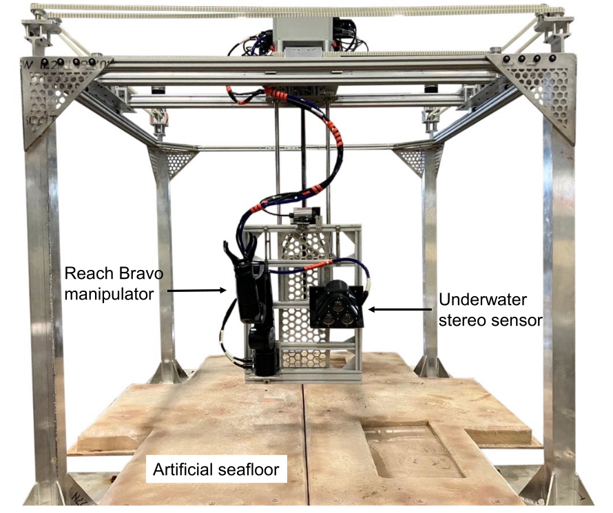
WAVE is a kinematically redundant system consisting of a 4-DOF positioning gantry carrying a 6-DOF electric subsea manipulator and steovision sensor. All components beneath the XY-frame are waterproofed such that they can all be submerged and used in underwater manipulation studies.
The positioning gantry is designed such that it replicates motions typically seen on inspection class remotely operated vehicle (ROV). With repsective motions being generated in the surge-sway-heave-yaw directions and each axis being powered by a encoder based servo motor. With the addition of a manipulator and perception sensor, the system as a whole can further replicate a full UVMS.
We also incorporated an additional DOF in the pitch direction by designing a compliant mechanism that closely replicates the dynamic coupling effects seen between a manipulator and vehicle body on a UVMS.
Advantages of WAVE
Each servo motor on the testbed frame can be individually tuned based on the respective load on its shaft. See Tuning Testbed Motors for more information.
If submersion of the WAVE system is not possible, the passively compliant component characteristics can be modified to compliment a dry lab setup. See Compliance for more information.
WAVE can maintain accurate ground truth localization through encoders at each of its joints.
Disdvantages of WAVE
Common UVMS have two passively stable unactuated DOF: pitch and roll. The current version of WAVE only includes passive compliance in the pitch axis.
1 - Using WAVE
Instructions on how to operated the WAVE
The current version of the testbed does not have software/hardware limits on axes travel. When driving the physical testbed, be away of the travel of each axis to ensure no crashing at the end of their travel.
Build the testbed software
The ROS testbed driver runs as a single node. To run the software:
Install the software using catkin and add it to your workspace:
cd testbed_ws
catkin build
source devel/setup.bash
Ensure the TESTBED_SITE environment variable is set and that there’s a corresponding ${TESTBED_SITE}_config.yaml which gives the Clearpath motor serial numbers.
Run the testbed launchfile:
roslaunch testbed_driver testbed.launch
By default the driver runs all four axes but individual axes can be disable if they are not available:
bash roslaunch testbed_driver testbed.launch enable_yaw:=false
Teleoperating the testbed
Launching the joystick node
A simple joystick-based remote control node is provided. Right now we are using Logitech joysticks, the axis mapping may be different on XBox controllers.
In a separate window, source the Testbed workspace:
source devel/setup.bash
Run the teleop node:
roslaunch testbed_teleop teleop.launch
When done, ctrl-C to quit.
Operating the game controller
In the current version, all four axes start in a velocity control mode, with all axes disabled.
The left shoulder button enables all axes.
The right shoulder button disables all axes.
The left joystick controls the CoreXY axes.
The right joystick (left-right) controls the Yaw axis.
The right joystick (up-down) controls the Z-axis.
The start button switches the system between velocity and position mode. The initial press will switch the system to position mode. This mode is highly untested and will cause the testbed to immediately try to return to zero position … !!do not use!!. Pressing start again will put the unit in velocity mode.
Zeroing Testbed Motors
The current method for zeroing the testbed is in its beta phase and is as follows:
Identify a location within the physical testbed workspace that you would like to set as your “zero” or “home” position (i.e. bottom left corner, bottom right corner, etc).
Identify a z-height that you would like your “zero” to be.
Identify a yaw “zero” orientation.
Enable the testbed.
Use the controller to manually drive the testbed to the identified “zero” location (X, Y, Z, Yaw).
In another terminal enter the following command for the desired axis value: yaw, zmotor, or corexy (which does both motors).
rosrun testbed_driver tbc zero {axis}
1.1 -
The ROS testbed driver runs as a single node. To run the software:
Install the software using catkin and add it to your workspace:
cd testbed_ws
catkin build
source devel/setup.bash
Ensure the TESTBED_SITE environment variable is set and that there’s a corresponding ${TESTBED_SITE}_config.yaml which gives the Clearpath motor serial numbers.
Run the testbed launchfile:
roslaunch testbed_driver testbed.launch
By default the driver runs all four axes but individual axes can be disable if they are not available:
A simple joystick-based remote control node is provided. Right now we are using Logitech joysticks, the axis mapping may be different on XBox controllers.
In a separate window, source the Testbed workspace:
source devel/setup.bash
Run the teleop node:
roslaunch testbed_teleop teleop.launch
When done, ctrl-C to quit.
Operating the game controller
In the current version, all four axes start in a velocity control mode, with all axes disabled.
The left shoulder button enables all axes.
The right shoulder button disables all axes.
The left joystick controls the CoreXY axes.
The right joystick (left-right) controls the Yaw axis.
The right joystick (up-down) controls the Z-axis.
The start button switches the system between velocity and position mode. The initial press will switch the system to position mode. This mode is highly untested and will cause the testbed to immediately try to return to zero position … !!do not use!!. Pressing start again will put the unit in velocity mode.
1.3 -
Then there would be some text here to discuss the section
2 - Hardware
See the below sections for further detail about each subcomponent of the WAVE testbed
Core-XY
To generate motion in the XY-plane, the testbed uses a Core-XY belt/pulley transmission system to drive a central carriage along linear rails.
With the Core-XY system, individual actuator motion (i.e. one servo rotating and one servo fixed) generates diagonal carriage movement and paired actuation motion generates coordinated “left”, “right”, “forward”, or “backward” movements. Compared to a traditional gantry design, the Core-XY system allows the larger X-Y actuators to remain fixed to the frame, reducing the mass of the moving portion of the system.
The XY frame moves the mobile trolley carriage that includes an electrical junction box, the Yaw and Z-axes, and a suspended aluminum frame with the underwater manipulator and perception sensor.
The XY frame is also mounted to four welded square aluminum legs with slotted feet for anchoring to the floor which results in an overall testbed dimension of 1.95 m x 1.83 m x 1.55 m.
Yaw
The yaw axis is housed within the mobile carriage and its servo motor rotates a slewing ring through a 5:1 belt and pulley system, which in turn rotates the vertical column.
Z-Axis
Within the vertical column is the Z-axis servo motor, which drives the Z motion stage (with the manipulator and perception sensor) using a leadscrewwith a total travel length of 0.75 m.
The actuator integrates with the leadscrew via a 5:1 planetary gearbox and flexible coupling to ensure smooth motion of heavy payloads attached to this motion stage.
Compliance
A key feature of WAVE is physical embodiment of realistic dynamic coupling between the manipulator and vehicle body through passive compliance. To design a compliant pitch mechanism for WAVE, we constructed a rigid body model of an idealized ROV with a manipulator in a Julia based hydrodynamic simulation.
Within this simulation, the dynamic coupling between the vehicle and manipulator were studied by evaluating the stiffness interaction on the vehicle imposed by the manipulator. The simulation inputs were the manipulator’s collision free planar workspace, and the output was the manipulator’s configuration based center of mass (COM) and the vehicle’s resultant pitch at equilibrium.
The resultant simulated stiffness parameters drove mechanical design for pitch compliance.
2.1 -
2.2 -
2.3 -
2.4 -
3 - Software
The testbed software communicates with the testbed hardware.
The majority of the testbed control software is ROS-based, although there are some peripheral utilities which run outside of ROS for simplicity. The ROS-based software driver speaks to the motors and interfaces with the ROS Control stack to allow the testbed to be driven by tools like MoveIt!.
The file software archiecture is described in the detailed software description
The core Testbed software is stored in two Gitlab repos:
testbed_hw is concerned with driving the actual Testbed, including communicating with the Clearpath motors.
testbed_sw contains configuration files which describe and configure the testbed. Some configuration is specific to the hardware testbed (for example, which Clearpath motors drive which axes). Other configuration files are used for Gazebo simulation, and some are used for for hardware and sim operation.
3.1 - Testbed Software Installation
Software installation for the testbed
Install the ROS software
These instructions assume you have at least a basic ROS install, C/C++ compilers, etc
Get prerequisities:
apt install -y python3-vcstool
On a system running ROS Noetic, create a ROS workspace and checkout out testbed_hw:
mkdir -p testbed_ws/src
cd testbed_ws/src
git clone https://gitlab.com/rsa-manipulation-testbed/testbed_hw
Then checkout the other dependencies using the .rosinstall file found in that repo, then use rosdep to get any other dependencies
The Clearpath communication hub requires a special device driver. This must be built and installed manually any time the system kernel is updated. If the driver is not installed, the system hub will show up as a /tty/devACMx device. If installed properly, the hub will show up as a /dev/ttyXRUSBx device.
A short script install_kernel_modules.sh is included in testbed_hw/clearpath_sc_ros which will automate this building process. It can be run from a checkout of tha repo or:
Most of the configuration should be set to appropriate default values, with the exception of the Clearpath motor mapping, which must be set for each Testbed site.
Motor mapping
The software must be told explicitly which Clearpath motors correspond to which testbed axes. This is done through a config file in testbed_config called {TESTBED_SITE}_config.yaml where {TESTBED_SITE} is a descriptive name for a given testbed installation.
The file contains four config params which give the Clearpath serial number fo the for axis. For example uwapl_config.yaml is:
## Clearpath motor serial number for APL Testbed#yaw_sn: 70403992zaxis_sn: 73003302corexy_a_sn: 65800963corexy_b_sn: 66102023
The testbed.launch assumes that the argument testbed_site is set, or as a default will look for an environment variable TESTBED_SITE
!!! We strongly suggest that the environment variableTESTBED_SITEbe set automatically on the user account/computer which drives the testbed.
Clearpath motor configuration
The clearpath_config.yaml file sets motor paramters within the Clearpath motor itself. This includes velocity, acceleration, current and jerk limits. As these limits are set in the motors they are absolute limits on motor performance.
ROS Controller configuration and tuning
The testbed_controllers.yaml file describes the motor control interfaces exposed by the Testbed to the ROS Control system. Since the testbed uses position control loops which run within ROS this includes PID parameters for those control loops, as well as joint limits to be enforced by the software controllers.
3.2 - Bravo Manipulator Driver
Software installation for the Bravo Manipulator
Follow the steps listed in the README.md for intial usage of the Bravo manipulator.
3.3 - Tuning Testbed Motors
Download Clearpath software and run the auto-tune software
Teknic offers a software API to interface directly with their integrated servo motors. Amongst many actions within the software, there is an Auto-tune command sequence that enables tuning of individual motors based on their mechanical setup.
Download the ClearView software by:
Registering an email with Teknic to access the software and documentation.
Clicking the dropdown menus labeled ClearPath/Software/ClearPath-SC Series Motor Setup…
Download and install the ClearView software for your respective computer operating system.
There is also the option to download and install the stand-alone USB port for communicating with the ClearPath-SC motors if not using a computer that does not have ClearView installed. An instance of this installation is performed in the Software/Testbed Software Installation instructions.
Run the Auto-tune command:
Plug the Comms board into your computer.
Power on the servo motors and Comms board.
Open ClearView.
Select the motor you want to tune.
In the upper-menu boarder, select the dropdown menu Setup.
Select Auto-tune….
Follow the API instructions to complete this function.
Be aware that the auto-tune function will toggle motion on the selected servo. Be sure to stay away from any moving parts and that the servo axis is clear of any obstructions to avoid collisions.